
")
 Despite all the fascination that left-hand turning spontaneously exerted on me, I of course didn't know whether it would give me countless hours of joy and relaxation over many years or whether it would turn out from the first few attempts that there was actually no significant difference to creating would be noticeable on the normal lathe. So I decided to build my first left-hand lathe as simply as cheaply and as space-saving as possible. In addition to a particularly simple solution, I was of course also looking for a variant that could be implemented quickly, because I was really excited to see my first left-hand turning results.


Let's think first...
First, I carefully studied all the information that I had collected so far in order to best take into account all of the already brief information and advice. Unfortunately, I was unable to implement the first essential feature of a left-hand lathe, the spindle bearings with plain bearings, neither in the short term nor free of charge. I also pondered for a long time about the spindle thread, which would ideally have to be a left-hand thread. If I had a spindle with a left-hand thread made somewhere, I would always have to rely on outside help to make various chucks and other accessories.
...then let's begin
That's why I finally decided to make my chucks so that they can be attached to a cylindrical stub shaft (diameter 10mm). I machined the holes to finished dimensions with a suitable reamer. To create the necessary frictional connection between the spindle and the chuck, I used an M4 grub screw, which I screwed into a threaded hole cut into the side of the chuck. However, initial attempts with this simple solution soon revealed some disadvantages. Since the grub screw has to be tightened relatively tightly so that the chuck does not come loose when turning, I soon found impressions of the screw tip on the spindle stump. In addition, the screw slots of the grub screws could not withstand the stress of frequent chuck changes for long. I therefore screwed a ring-shaped recess into the chuck holes using a tiny hook steel to create space for a ring-shaped, bent piece of watch spring steel, which is “snipped” into this recess. This effectively protects the spindle surface from damage caused by the grub screw. I replaced the grub screws with ones with a hexagon socket instead of a slot and a small cutting ring instead of a tip on the other side. As a lining key, I use a suitable Allen key with a T-handle so that I can apply sufficient force without putting unnecessary strain on my wrist. After all, I have to screw the chuck on and off every time I change the workpiece, because driving the workpieces into the chuck directly on the spindle would definitely overwhelm my simple design.
A speed controller is needed
As can be seen from the nameplate (Figure 3) of the motor used, it has a nominal speed of 8000 1/min. Even if one takes into account that the advantages of left-hand turning are particularly noticeable on workpieces with very small diameters, the resulting peripheral speed is somewhat high. When I was looking for a solution, the circuit shown in Figure 5 immediately came to mind. I had already set it up a few times for friends and acquaintances in order to upgrade the “legendary” GDR do-it-yourself drill “Multimax”. What is interesting about this circuit is that it is a “real” speed control, but does not require a speedometer. The circuit only works with a half wave of the alternating current and the armature counter voltage of the universal motor serves as a measure of the actual speed.
The circuit diagram of the speed controller
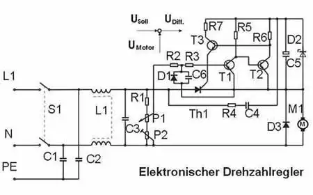
Figure 6: The circuit of the electronic speed controller comes from a "circuit collection for the radio amateur" from the military publishing house of the former GDR and was originally designed for subsequent installation in the "legendary" hand drill "Multimax".
Download circuid diagram "Drehzahlregler"
Disclaimer:
The circuit shown serves exclusively as a detailed description of my self-made left-hand lathe. I assume no liability for damage of any kind, e.g. caused by improper reproduction. I also don't know anything about any third-party rights to this circuit.